Dienstag, 12. Mai 2015

Final project - final post


At last everything is working! In order to get the bot working we had to tweak two things:
  1. the wheels were not fixed in the walls of the bot so it could not go in a straigh line. By adding tape to the motors, we were able to make a better fit and fixed the wheels.
  2. When all the parts had come together, the bot would not draw/drive anymore. The problem was that all the parts were pulling too much energy. So by putting two batteries in series we were able to give the bot enough power. 


Explain whether your project ended up as you initially envisioned 
The final project does differ from our envisioned goal. We have not made use of the WiFi Shield and, therefore, cannot read APIs and make the robot move based on that data. So the final project is a "lite" version of our initial idea.

However, having the bot run "offline" is a good starting point to learn more about robotics.

What challenges did you face? 
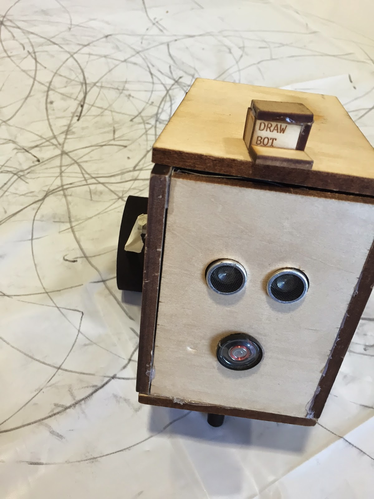
This project had a big physical component to it so we had to figure that out before actually starting the coding (which then only was the last push). The hardware added another dimension to the project and it made de-bugging really complicated because the errors became "invisible". The only way to really figure out the poblems is to do a lot of testing of the cables and isolating and testing all parts individually. For example, the range sensor stopped working at some point and we weren't entirely sure why. So we wrote a sketch just for the sensor and ran some test until we figured out that the casing was pushing the ultrasonic receiver and transmitter at an angle apart from one another. This caused the sensor to not read properly. Althought the bug is fairly simple in theory, figuring out what caused took some time.

Any lessons learned?
Yes, we should have prototyped everything on a breadboard rather than throwing everything together in the actual robot. Going for the bot right away makes you run into a lot of problems and debugging very complex.

Any last thoughts about this project?
Building the bot really was a challenge because I have never dabbled in robotics before. However, it is very rewarding when things actually work out in the end. I hope to learn more about soldering and rewiring shields in the future so I can actually connect it to APIs to make it draw based on data it receives.

Any last thoughts about physical computing?
At the beginning of this semester I really had no clue about physical computing or Arduinos and I really didn't  expect to be building a robot by the end of the semester. That being said, I think there is so much more to be explored and I am very glad to have a more entertainting "real-life" application to programming. That is something I have been waiting to explore for a long time! 

Dienstag, 5. Mai 2015

Final Project - post 2

In the last week, we did the following things:
- finalized the concept (add/remove parts)
- laser cut the robot's casing
- figure out and solder the circuit
- work on the code

Here's a short video update:

So let me go through the above points step by step to give you an update.

Final concept
Natalyia and I decided to keep it simple and only used the motor shield. We wanted to make sure that the robot does what he is supposed to do (which is drawing) in a controlled fashion before potentially hooking it up to other sources of input (such as weather or date APIs).
Also, we are using gear DC motors now (instead of normal DC motors) to give the robot more torque. To increase the bot's ability to drive more, we added a little metal ball caster wheel, so the bot is now balancing on the two wheels and the caster wheel.

Laser cutting the parts
This part took some trying and testing to get the measurements perfectly down. We wanted to glue as few parts as possible so we made exact measurements to give the parts a good fit. This worked in most cases (range sensor, wheels, one vibration motor) but we had to use a little duct tape in other instances.

Figuring out the circuit
For space reasons we did not include our breadboard in the bot. Instead we used a perf-board and soldered the wires together. Altough more space efficient, it took more fiddling with the circuit to make it work properly. Also, the circuits can get really messy using this approach:
wiring

Working on the code
Once the circuit was done, we had to start working on the code. To make the bot more interactive, we had to create conditions for the bot to react to us. So for example, we made a little hat the bot gets excited about and starts to draw when it's wearing it. We are also using the range sensor to influence the the drawing; so when you get too close, the bot will "freak out", drive away and then resume drawing the pattern we programmed it to do.

Drawbot's hat

What's next?
Now we only need to fine-tune parts of the code for the bot to function correctly. Once that is done, we are ready to present :-)

Freitag, 24. April 2015

Final project - first post


For the final project Nataliya and I want to build a (potentially moody) drawing robot. The robot will be powered by 2 DC motors that spin at different speeds depending on the input it is getting from a variety of sources (analog sensors and potentially weather and date APIs). The drawbot will be supported by a pencil on the opposite end to where the wheels are attached. This will produce a triangle and thus give the support for the drawbot not to tip over. Here is a schematic drawing:


Nataliya and I will probably use the laser cutter to print a box that will house the Arduino, the wifi or motor shield, and all the sensors. Here is a front view:


And a side/top view:


We have not yet decided on the sensors. However, it would be nice to use sensors that would elicit a certain response in drawbot. For example, when you get too close, he will scurry away and in the process draw a “picture”. Or when it is dark in the room, drawbot will move rather slowly and  produce a different painting based on the speed. Other sensor I am thinking about at the moment are microphones to measure the volume in the room. However, I am unsure about the sensitivity of the microphone (I haven’t worked with it before) so I don’t know how well drawbot could react to that.

If we manage to connect drawbot to the internet, it would be funny to give him different moods depending on the time of day and the weather. He could be equipped with a speaker and he could tell you that he’s in bad mood because of the weather and now is going to draw something in a slow speed because of that.

Target audience:
There is no specific target audience in terms of age. Anyone who is entertained by a little device reacting to environmental influences and drawing a “picture” as a result.

Does it fulfil an existing need?
No, not really.

Does it enhance interaction or human behavior?
No, it’s more like a toy than a helpful device

What parts are needed?
I have looked at two parts that would be more or less expensive. However, I am unsure if they can work together because they use the same pins. So I will have to look into that more. The parts are:
  • a wifi shield ($50)
  • a motor shield ($25)
The good news is that the eLab has a wifi shield which we could probably use for this project. However, if we end up using both shields, we might have to buy our own shield because we have to change some pins on the board and solder them back on differently.
The motor shield is available on amazon and can be delivered within two days.


what, if any, hardware, mechanical devices, and/or movements will your project involve?
The wheels on the arduino will spin (rotational movement) with the DC motors and cause the drawbot to move (translative movement).


what, if any, Arduino, Processing, or other software applications or libraries will your project use?
Well, it depends on the shield we are using. The wifi shield requires the wifi library and SD card library. The motor shield requires the AFMotor library. If we end up giving drawbot a voice, we need a voicelibrary.


Team members:
Nataliya and I will work together on this project. She is:
  • a senior in CAS majoring in Economics with a minor in Web Development and Applications
  • great at manufacturing physical component 
  • the conceptual part is done by the two of use. In our last project she constructed the physical aspect while I did the coding. Maybe we will switch it up this time but that depends on what sensors and shields we will actually end up using.  
I am:
  • a senior in Gallatin and my concentration is "Understanding Modern China through Internet Censorship" and I will hold a minor in Web Development and Applications as well 
  • good at brain storming and conceptualizing 

Donnerstag, 23. April 2015

Data Visualization Lab

Experiment #1: single data set - internet users in China

In my first dataset I used the amount of internet users in the PRC from 2014-2000. I used the XlsReader library to loop through an xls document and then printing out each bar using the beginShape(QUADS) funciton to draw the bars. 

This is the raw data that I have obtained from: http://www.internetlivestats.com/internet-users/china


And this is the graph that resulted from reading out the data


Experiment #2: two data sets - NYC population and water consumption 1979/80 - 2009/10


For my second data I compared the average water consumption/day with the NYC population. Again, I used the XlsReader library to read the info. However, since I had to read two different data sets, I had to alter the code from the first experiment. For each dataset I first read all values into an array and then printed both lines in the draw() setup. 
The data was taken from:
http://en.wikipedia.org/wiki/Demographic_history_of_New_York_City; and
https://data.cityofnewyork.us/Environment/Water-Consumption-In-The-New-York-City/ia2d-e54m

 Here is the raw data:
NYC population from 1980-2010

Average water consumption in million gallons/day from 1979-2009

This is the data visualized:

Experiment #3: Twitter real time
For my third experiment I used the twitter API and wanted to use a 3D animation that showed the frequency of certain hashtags without showing absolute values. I stumbled across the GWOptics library for 3D animations in Processing which I can highly recommend. I combined a code of theirs with a Twitter API code (using Twitter4j) that I have used earlier for my midterm. 

I used three different hashtags which I expected to have different post-frequencies (low, medium, and high) to produce three different animations. Here we go:

low frequency - #MakeTheGroundswell


medium frequency - #PhysicalComputing


high frequency - #Design


The more posts there are, the higher the amount of waves as can be seen in the videos. This form of visual represenation seems to be the most interesting even though the least informative/accurate.


Dienstag, 21. April 2015

Mechatronic Device


For this assignment I was trying to see how many different forms of movement you could create with just one single DC motor (rotation). I used the laser cutter to make cogs that would help me in this process. I also built a box with two holes: one hole would hold the DC motor attached to a cog, while the other used to fix a rod running through a cog. Here's a short demo:


This is a simple sketch of the entire setup:


So the DC motor powered the rotation of the rod. I then attached a thread to the top of the rod. The rotation of the DC motor would then reel in the thread, transforming rotation to translation. At the other end of the thread, I attached a piece of paper to better see the translative movement. Additionally, I wanted to explore direction of translation and how to easily manipulate it, so I used a second rod, to influence the path the piece of paper would travel. Below is a picture from the right side:


As soon as the DC motor turns, the paper would first travel towards you, then spin around the rod and then change direction to travel towards the direction of the DC motor in the back.


Here's a video from the front demonstrating the result.


During the building I also encountered a few problems with using the 5V DC motor:
- the motor is not strong enough to power the cogs at a slower speed (the initial power given to the cogs has to be fairly high in order for them to keep moving).
- with my setup, it is difficult to pull big weights because any weight changes the angle of the rod in the wooden box. As a result, the cogs jam. So currently I am only able to pull small weights.

On a positive note, I learned how to solder because the wires of the DC motor were too short and I kept on encountering problems with the DC motor disconnecting from the breadboard. 

If you have any questions, please reach out to me!

Montag, 13. April 2015

Motor Labs

Controlling a Servo Motor from Processing


This is a video of me controlling the servo from Processing. The source code was taken from class so I won't post it here. However, it can be found here: http://cs.nyu.edu/~amos/courses/physical_computing/arduino-platform/controlling-a-servo-motor-from-a-processing-program_03042013.html


Controlling a DC motor with a Potentiometer


Here a DC motor is controlled by a potentiometer.  The source code is here:

The Arduino reads the analog input from the potentiometer which then is mapped to match the 0 to 255 of the DC motor. After, the pot value is sent to the DC motor and the speed is controlled.


Control the speed of a toy motor from processing

It is kinda hard to see here that the DC motor is moving but it is (you see it shake at 0:03 when it turns on). The code for this task was a mix of the above two. I used the processing code from the first one and removed the potentiometer from the second one and replaced it with serial communication. The arduino code is below: